Part of the RF chain series — a page per block. The coupler sits after the isolator and before the antenna, watching what goes out and what comes back.
The RF chain, block by block —Antenna · Filter · LNA · Mixer · LO · IF & ADC · PA · Isolator · Coupler · Overview
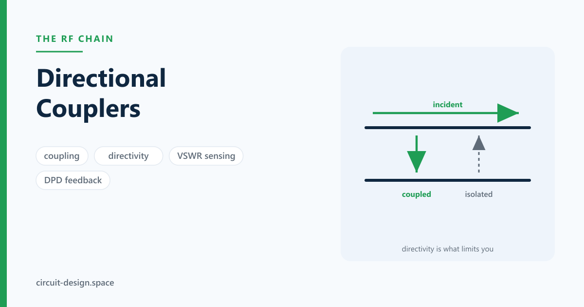
A directional coupler takes a small, known fraction of the power travelling in one direction and ignores the power travelling in the other. That directional selectivity is the whole point, and it is what makes it possible to measure forward and reflected power separately on a line that carries both at once.
Unlike an isolator, a coupler is perfectly reciprocal. It does not break reciprocity; it exploits the geometry of coupled lines so that the coupled signals from the two directions add at one port and cancel at the other.
1. The four ports and the three numbers
A coupler has an input, a through (transmitted) port, a coupled port, and an isolated port:
| Parameter | Definition | Typical |
|---|---|---|
| Coupling factor | — how much reaches the coupled port | 10, 20, 30 dB |
| Directivity | ratio of coupled-port output for forward vs reverse drive | 20–40 dB |
| Isolation | input to isolated port; $= $ coupling directivity | derived |
| Insertion loss | input to through port | coupling loss + dissipative loss |
| Return loss | at each port | 20 dB+ |
A 20 dB coupler passes 99% of the power through and samples 1%. The insertion loss from the coupling alone is only 0.04 dB — which is why a coupler can sit permanently in a transmit path.
The general statement, since the choice of coupling factor is usually made casually and shouldn’t be. With the through-path loss due to coupling is :
| Coupling | Power through | Coupling loss | |
|---|---|---|---|
| 3 dB | 0.708 | 49.9% | 3.02 dB |
| 6 dB | 0.501 | 74.9% | 1.26 dB |
| 10 dB | 0.316 | 90.0% | 0.46 dB |
| 15 dB | 0.178 | 96.8% | 0.14 dB |
| 20 dB | 0.100 | 99.0% | 0.044 dB |
| 30 dB | 0.032 | 99.9% | 0.004 dB |
Below about 15 dB of coupling the loss stops mattering, and above about 10 dB it starts to. So the real constraint on coupling factor is at the other end: the coupled port has to deliver enough signal for whatever measures it. A 30 dB coupler on a 1 W transmitter delivers 0 dBm to the detector — comfortable. The same coupler on a 100 mW transmitter delivers −10 dBm, which is inside the noise of a cheap log detector at low levels. Choose the coupling from the detector’s dynamic range, then check the through-loss is acceptable; almost everyone does it the other way round.
2. Directivity is the parameter that matters, and datasheets bury it
Coupling is a design choice. Directivity is a limit.
Directivity is how well the coupler distinguishes forward from reverse. If it is finite — and it always is — then some of the reverse wave leaks into the forward-coupled port, and your measurement of forward power is contaminated by reflected power (and vice versa).
The practical consequence: directivity sets the best return loss you can measure. If the coupler has 25 dB of directivity, you cannot reliably measure a return loss better than about 25 dB, because at that point the leakage through the coupler is the same size as the real reflected signal. The measurement uncertainty is worst when the two are comparable and depends on their relative phase.
That is worth quantifying, because the error is much larger than people expect. The leakage adds to the true reflection as a vector of unknown phase, so the measured reflection lies anywhere between and :
| Directivity | True return loss | Measured range | Spread |
|---|---|---|---|
| 20 dB | 10 dB | 7.6 … 13.3 dB | 5.7 dB |
| 20 dB | 15 dB | 11.1 … 22.2 dB | 11.1 dB |
| 20 dB | 20 dB | 14.0 dB … ∞ | unbounded |
| 25 dB | 20 dB | 16.1 … 27.2 dB | 11.1 dB |
| 30 dB | 20 dB | 17.6 … 23.3 dB | 5.7 dB |
| 40 dB | 20 dB | 19.2 … 20.9 dB | 1.7 dB |
| 40 dB | 25 dB | 23.6 … 26.7 dB | 3.1 dB |
Two things to take away. When the directivity equals the return loss you are measuring, the answer can be anything from “twice as bad” to “perfect” — the leakage can exactly cancel the real reflection and show infinite return loss, which is the origin of the mysteriously perfect antenna that stops being perfect when you move the cable. And useful accuracy needs about 15–20 dB of directivity margin over the return loss being measured: to hold a 20 dB measurement to ±1 dB you need a 40 dB coupler, which is why a return-loss bridge with 40+ dB of directivity costs what it does.
The same arithmetic, run backwards, is the VSWR-monitoring calculation:
| Measured return loss | | Load VSWR | |—:|—:|—:| | 6 dB | 0.501 | 3.01 | | 10 dB | 0.316 | 1.92 | | 14 dB | 0.200 | 1.50 | | 20 dB | 0.100 | 1.22 |
A VSWR-protection threshold is usually set at 2:1 or 3:1, which is a 10 dB or 6 dB return loss — comfortably inside what even a 20 dB-directivity coupler can resolve. Protection is an easy measurement; characterisation is a hard one. Do not buy a laboratory-grade coupler to implement a trip threshold, and do not use a trip-threshold coupler to characterise an antenna.
This is why a VNA’s raw directivity is one of its headline specifications, and why calibration matters so much — the calibration step measures the directivity error and removes it mathematically, achieving effective directivity far beyond the hardware’s raw figure.
A related trap: isolation and directivity are different things and are often confused. Isolation is measured to the isolated port; directivity is the difference between coupling and isolation. A datasheet quoting only isolation is not telling you what you need, because a tightly coupled device can have high isolation and poor directivity.
3. The types
| Type | Bandwidth | Coupling | Notes |
|---|---|---|---|
| Coupled-line | octave+ | loose (10–30 dB) | the printed default; a quarter-wave coupled section |
| Branch-line | 10–20% | tight (3 dB) | quadrature outputs, easy to print |
| Lange | octave+ | tight (3 dB) | interdigitated; needs bond wires or fine lithography |
| Rat-race (hybrid ring) | 20–30% | 3 dB | gives sum and difference ports |
| Wilkinson divider | broad | 3 dB split | not directional — a divider, with isolation between outputs |
| Directional bridge | DC–multi-GHz | resistive | very broadband, lossy; used in VNAs and return-loss bridges |
| Waveguide (Bethe-hole, multi-hole) | wide | various | high power, low loss |
Two clarifications that save confusion. A Wilkinson is a power divider, not a directional coupler: it splits equally and gives isolation between the two outputs, which is what you want for feeding an antenna array or combining two amplifiers. A 90° hybrid (branch-line or Lange) is what makes a balanced amplifier work, because reflections from the two identical devices recombine into the terminated port rather than back toward the source.
4. What they are used for
Measuring forward and reflected power. The classic use. Two couplers back to back, or one dual-directional coupler, give simultaneous readings, and from their ratio you get the load VSWR in real time. This feeds:
- VSWR protection — back off the PA drive if the antenna is detuped or disconnected. This is the alternative to an isolator: it detects the problem rather than absorbing it, with no forward loss.
- Antenna fault monitoring in deployed systems.
- Automatic level control on the forward path.
Digital pre-distortion. A DPD system needs to observe what the PA actually transmitted so it can compute the inverse nonlinearity. The coupler is that observation path, and its directivity matters: reflected energy leaking into the DPD feedback makes the algorithm correct for something that is not the PA’s distortion.
Signal injection for test. A coupler lets you inject a test tone into a live path without breaking it.
Instrumentation. Every VNA has directional couplers or bridges at its heart — separating incident from reflected is exactly the measurement it performs.
5. Design and layout notes
Printed coupled-line couplers are a distributed EM problem, not a lumped one: the coupling depends on the even- and odd-mode impedances of the coupled pair, which depend on trace width, spacing, and the dielectric above and below. The synthesis equations are short —
with and a coupled section a quarter wavelength long at band centre. Putting numbers to them shows immediately where printed couplers are easy and where they are not:
| Coupling | Practical on a board? | ||
|---|---|---|---|
| 3 dB | 120.9 Ω | 20.7 Ω | edge-coupled microstrip cannot do it — needs a Lange or broadside coupling |
| 6 dB | 86.7 Ω | 28.8 Ω | hard; gaps in the tens of microns |
| 10 dB | 69.4 Ω | 36.0 Ω | achievable with care |
| 15 dB | 59.9 Ω | 41.8 Ω | comfortable |
| 20 dB | 55.3 Ω | 45.2 Ω | easy — and tolerant, because the modes are close |
| 30 dB | 51.6 Ω | 48.4 Ω | easy, but the coupled signal is small |
Tight coupling needs a small gap, and a small gap is where fabrication tolerance lives. At 3 dB the required odd-mode impedance of 20.7 Ω implies edge spacing far below what a standard process can etch repeatably, which is precisely why the Lange coupler — interdigitated fingers that multiply the coupled edge length — exists, and why broadside (stacked-layer) coupling is the other answer. At 20 dB the mode impedances differ by 10 Ω and a 25 µm etch error barely moves the result. If your design permits loose coupling, take it.
Two further practical consequences:
- On microstrip, the even and odd modes travel at different velocities because part of the field is in air. That velocity difference degrades directivity — often to 10–15 dB, which is poor. Stripline, with a homogeneous dielectric, does not have the problem. If you need directivity from a printed coupler, use stripline, or add compensation (wiggly lines, lumped capacitors at the ends) to equalise the modes.
- Field-solve it. Coupled-line dimensions at these tolerances are not a closed-form exercise, and the launches are part of it.
Termination quality on the isolated port sets directivity in practice. A coupler’s specified directivity assumes a good load on the isolated port; a mediocre termination reflects, and that reflection appears as leakage into the coupled port. On an integrated coupler this termination is internal; on a four-port device it is yours to get right.
6. Example parts
Couplers and hybrids are one of the clearest buy-don’t-build cases on a board: a surface-mount part occupies less area than a printed quarter-wave section below a few GHz, and arrives with its directivity specified. Illustrative parts; check current availability.
Surface-mount directional couplers:
| Part | Notes |
|---|---|
| Mini-Circuits DBTC-17-5+ | wideband bidirectional coupler in a small SMT package |
| Mini-Circuits SYDC-20-62HP+ | 20 dB, high power — the VSWR-monitoring workhorse |
| Mini-Circuits ZFDC-20-5+ | connectorised, for the bench |
| TTM/Anaren Xinger series | broad catalogue of SMT couplers and hybrids with good published data |
90° hybrids and Wilkinson dividers — different devices, adjacent shelf:
| Part | Notes |
|---|---|
| Mini-Circuits QCN series | SMT 90° hybrids — what a balanced amplifier or an I/Q modulator needs |
| Mini-Circuits SCN / SBTC splitters | Wilkinson-class dividers with real isolation between outputs |
| TTM/Anaren 3 dB hybrids | including Lange-class parts for wide bandwidth |
And the part the coupler exists to feed: a log detector or RMS power detector such as the Analog Devices ADL5511, AD8318 or LTC5596. The detector’s dynamic range and its temperature stability are usually what limits a VSWR-monitoring loop — not the coupler’s directivity — and choosing the two together is the right way round.
One thing to check on any datasheet: directivity is often plotted rather than tabulated, and the plot is often worse than the headline number at the edges of the band. If the specified directivity is quoted only at band centre, assume it degrades by 5–10 dB at the extremes, and design the measurement accuracy accordingly.
7. The pitfalls
- Reading isolation as if it were directivity.
- Choosing the coupling factor from the through-loss rather than from the detector’s dynamic range.
- Designing a tight-coupled printed coupler with gaps below the fabricator’s tolerance.
- Taking a band-centre directivity figure as valid across the whole band.
- Expecting to measure 30 dB return loss with a 20 dB directivity coupler.
- A microstrip coupled-line coupler with uncompensated mode velocities, and the resulting poor directivity.
- A poor termination on the isolated port, destroying the directivity you paid for.
- Confusing a Wilkinson divider with a directional coupler.
- Forgetting the coupler’s insertion loss in a transmit budget — small, but it is there.
- A DPD feedback path contaminated by reflected energy.
Further reading
- David Pozar, Microwave Engineering. Chapter 7 derives the coupled-line, branch-line and rat-race couplers from even/odd-mode analysis — the source of the synthesis equations above.
- Joel Dunsmore, Handbook of Microwave Component Measurements. The best treatment of directivity as a measurement limit, and of how calibration removes it.
- Robert Collin, Foundations for Microwave Engineering. For the field theory underneath coupled lines, if the network view is not enough.
- Chris Bowick, RF Circuit Design. Practical, and good on the measurement uses.
The RF chain, block by block —Antenna · Filter · LNA · Mixer · LO · IF & ADC · PA · Isolator · Coupler · Overview
Glossary
Branch-line coupler — A printed quadrature hybrid built from quarter-wave branches. Easy to lay out, tight (3 dB) coupling, and narrowband at 10–20% — the usual first choice when a 90° hybrid has to be printed rather than bought.
Coupling factor — : the fraction of forward power reaching the coupled port. A design choice rather than a limit, and the right way to choose it is from the detector’s dynamic range, then checking the through-loss is acceptable. Almost everyone does it the other way round.
Coupling loss — The through-path loss caused by the coupling itself, : 0.04 dB at 20 dB coupling, 3 dB at 3 dB coupling. Below about 15 dB of coupling it stops mattering, which is why a monitoring coupler can live permanently in a transmit path.
Directional bridge — A resistive bridge rather than a coupled line. Very broadband, DC to many GHz, and lossy — the construction inside most return-loss bridges and many VNA front ends.
Dual-directional coupler — Two couplers back to back in one package, sampling forward and reverse simultaneously. What a VSWR-monitoring loop actually wants, since the ratio of the two is the measurement.
Even- and odd-mode impedance — and , the impedances of the coupled pair when driven in phase and out of phase, with . Tight coupling needs them far apart — 121 Ω and 21 Ω at 3 dB — which is a gap too small to etch, and the reason the Lange coupler exists.
Isolation — Input to isolated port, equal to coupling plus directivity. Frequently the only one of the three quoted, and on its own it is not what you need: a tightly coupled device can have high isolation and poor directivity.
Lange coupler — Interdigitated fingers that multiply the coupled edge length, achieving 3 dB coupling over an octave where an edge-coupled pair cannot. Needs bond wires or fine lithography, which is the price of the bandwidth.
Mode velocity mismatch — On microstrip the even and odd modes travel at different speeds because part of the field is in air, which degrades directivity to 10–15 dB. Stripline, with a homogeneous dielectric, does not have the problem — so if a printed coupler needs directivity, use stripline or compensate.
Rat-race (hybrid ring) — A ring giving sum and difference ports. Distinct from the branch-line in that its outputs are in phase and antiphase rather than in quadrature, which is what a balanced mixer or a monopulse comparator wants.
Return-loss bridge — An instrument built around a directional element to measure match directly. Its directivity is its specification, because directivity is what limits the return loss it can resolve.
Through port — The main output, carrying what the coupling did not take. Its insertion loss is coupling loss plus dissipative loss, and on a 20 dB coupler the first term is 0.04 dB — small, and not zero, which matters in a transmit budget that is already tight.
Wilkinson divider — An equal power splitter with a resistor between the outputs giving isolation between them. Not a directional coupler, frequently confused with one: it splits, it does not distinguish forward from reverse.
Related
- The RF chain overview
- The power amplifier — what the coupler watches, and what DPD corrects
- The isolator — absorb the reflection instead of measuring it
- The antenna — the load whose VSWR you are monitoring
- S-parameters — where the four-port description comes from
Have a VSWR measurement you do not trust, or a DPD loop that will not converge? That’s what we do. Reach us at circuit-design.space.
circuit-design.space · +1-971-357-1400 · anovickis@circuit-design.space