Part of the RF chain series — a page per block. Neighbours: the LNA in front, the local oscillator driving it, and the IF chain behind.
The RF chain, block by block —Antenna · Filter · LNA · Mixer · LO · IF & ADC · PA · Isolator · Coupler · Overview
A mixer multiplies. That is the whole of it — and multiplication in the time domain is convolution in frequency, which is why two inputs produce sums and differences rather than one clean output. Everything difficult about mixers follows from the fact that you wanted one of those products and got all of them.
0. Why a mixer is a switch, not a multiplier
The textbook identity is the place to start:
— two products, each at half amplitude, which is the ideal 6 dB “conversion loss” of a perfect analogue multiplier splitting its energy two ways.
But nobody builds an analogue multiplier at RF, because a genuinely linear four-quadrant multiplier is slow, hot and non-linear where it matters. Every practical mixer is a switch: the LO does not multiply the RF by a sinusoid, it commutates it — flips its polarity at the LO rate. Multiplying by a square wave is multiplying by its Fourier series:
Two consequences, and they are the two facts that organise the whole subject.
The conversion gain of an ideal switching mixer is , or −3.92 dB — better than the multiplier’s −6 dB, because a square wave puts more energy in its fundamental than a sinusoid of the same peak amplitude does. A real double-balanced diode ring measures 5.5–7.5 dB of loss; the extra 2–3 dB is diode resistance, transformer loss, and power thrown into products you did not want.
The odd harmonics are in the series, so the mixer converts at them too. A signal at converts straight to the IF at only the amplitude, about 9.5 dB down — no nonlinearity required, no distortion mechanism, just the shape of a square wave. This is why a broadband receiver needs a pre-select filter even with a perfect mixer, and it is the single most common surprise in a wideband design: an interferer nowhere near the tuned frequency arriving at full strength through the third harmonic of the LO.
Driving the switch harder makes it a better switch — closer to an ideal square wave, less time spent in the soft region between states. That single sentence explains the LO-drive specification, the linearity behaviour, and why an under-driven mixer misbehaves in ways its conversion gain does not reveal.
1. The wanted output, and all the others
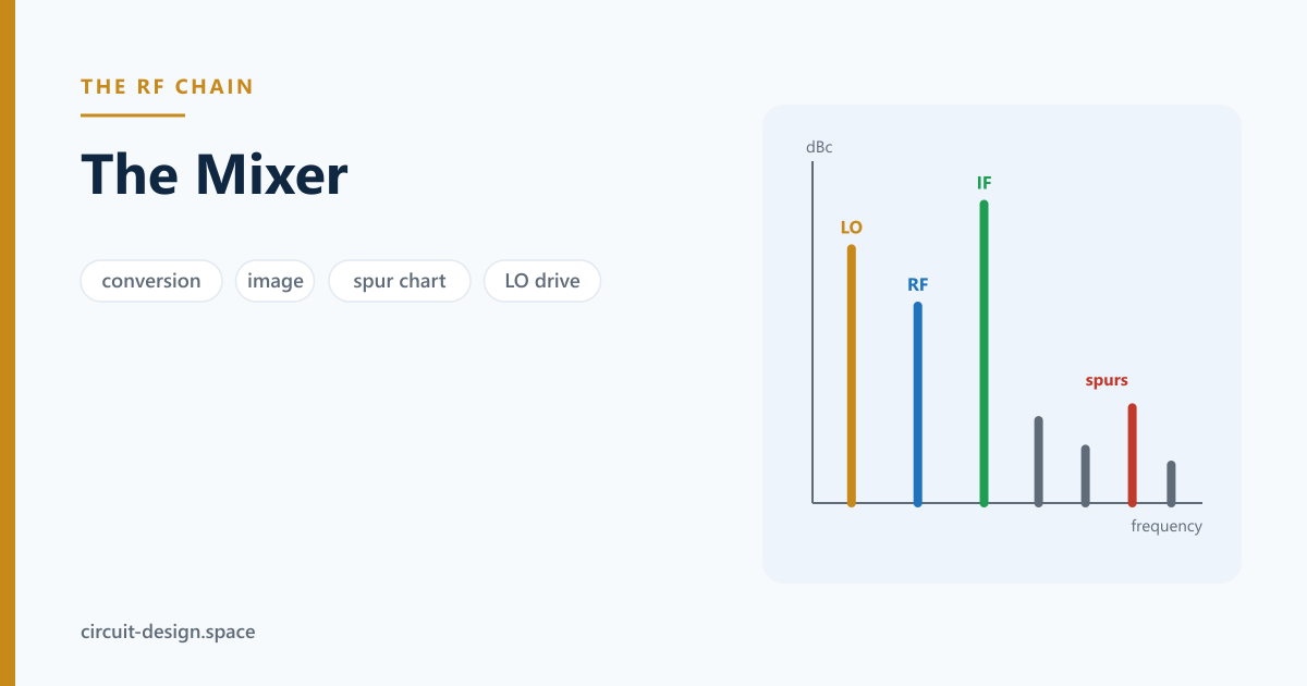
The wanted product is normally . Every other combination is a spur, and drawing the spur chart before fixing the frequency plan is the single highest-value hour in receiver design — moving an IF is free on paper and expensive in silicon.
Worked, with GHz and GHz, so the wanted IF is 400 MHz:
| Product | Frequency |
|---|---|
| LO − RF (wanted) | 400 MHz |
| LO − RF | 800 MHz |
| LO − RF | 1200 MHz |
| LO − RF | 1200 MHz |
A badly chosen plan lands a high-order spur inside the IF passband, where no filter can help because it is already at the frequency you are trying to keep.
How to actually draw the chart
The table above lists products. The chart answers a different question — which of them land in my passband — and it is a ten-line script, not a lookup:
- Sweep and from 0 to 5 or 7. Order is ; amplitude falls steeply with order, so anything above about 7 is usually below the noise unless the mixer is badly driven.
- Compute for the whole RF tuning range, not one frequency. A plan that is clean at band centre routinely fails at the band edge.
- Flag anything within half the IF passband of .
- Repeat with the RF replaced by each blocker frequency your system must survive. That sweep is the one that finds real problems.
For the plan above with a 40 MHz IF passband, the only in-band products are the wanted and a ninth-order that also lands at exactly 400 MHz — which is fine, because a ninth-order product in a well-driven double-balanced mixer is typically 80–90 dBc. A clean chart looks like this, and it is worth confirming rather than assuming.
The half-IF spur, which is what the chart is really for
The image is easy to think about and easy to filter because it is away. The half-IF spur is neither, and it is the one that catches people.
An interferer at — here, 2200 MHz — produces MHz, exactly the IF, through the second-order terms of both the interferer and the LO. It sits only 200 MHz from the wanted signal, where the image is 800 MHz away, so the pre-select filter that comfortably kills the image is of very little help against this one.
Its rejection depends on second-order balance — how well the mixer’s two halves match — rather than on filtering, which is a good argument for a double-balanced part and a very good argument for measuring it rather than trusting a datasheet. Its sibling, the half-IF at , works the same way from below.
2. The image, and the architectures built to deal with it
A simple mixer converts two input frequencies to the same IF: the wanted and the image . In the example above the wanted RF is 2.4 GHz and the image sits at 1.6 GHz.
Noise and interference at the image land directly on the signal. Even with no interferer present, thermal noise at the image degrades noise figure by up to 3 dB — the image band contributes noise and no signal.
Three answers, and every receiver architecture is a choice among them:
Image-reject filter ahead of the mixer. Simple, and the reason IF choice matters: the image is away from the signal, so a high IF makes the filter easy and a low IF makes it impossible. That is the fundamental superheterodyne trade — high IF for image rejection, low IF for channel selectivity — and it is why dual-conversion receivers exist.
Image-reject mixer (Hartley or Weaver). Two mixers driven in quadrature; the image cancels in the summation. Rejection is limited by amplitude and phase matching between the two paths, and the relationship is worth having in closed form. With an amplitude ratio between the paths and a quadrature error :
In decibels, for the combinations you actually encounter:
| Amplitude error | ||||
|---|---|---|---|---|
| 0.00 dB | 47.2 | 41.2 | 35.2 | 27.2 |
| 0.05 dB | 45.6 | 40.7 | 35.0 | 27.2 |
| 0.10 dB | 42.8 | 39.6 | 34.7 | 27.1 |
| 0.20 dB | 38.2 | 36.8 | 33.6 | 26.9 |
| 0.50 dB | 30.7 | 30.4 | 29.5 | 25.6 |
Read the table two ways. Untrimmed hardware lands around 30–40 dB — 0.2 dB and 1° is not a sloppy build, it is a good one, and it buys 36.8 dB. And the two errors do not add up symmetrically: at 5° of phase error, fixing the amplitude entirely gains you 1.6 dB and is a waste of effort. Find out which one dominates before trying to improve either. Beyond about 40 dB you are into calibration — measure the imbalance and correct it digitally — not into better components.
Zero-IF or low-IF. Put the LO on the signal, and the image is the signal’s own mirror image. This removes the image filter entirely and moves the problem to DC offset, flicker noise, LO self-mixing and I/Q imbalance. It dominates integrated receivers because those problems are tractable in silicon and a high-Q image filter is not.
Zero-IF, and the three things that replace the image problem
Worth spelling out, because “no image filter” makes zero-IF sound free and it is not.
LO self-mixing produces a DC offset that sits on top of your signal. The LO leaks out of the mixer’s LO port, reflects off the antenna or radiates and re-enters through the RF port, and mixes with itself — producing DC. The wanted signal is also at DC. Worse, the leakage path changes as the environment changes, so the offset is time-varying and cannot simply be calibrated once. The countermeasures are high LO-to-RF isolation, AC coupling with a corner low enough not to eat the modulation, and continuous digital offset tracking.
Second-order distortion becomes a first-class specification. In a superhet, IM2 products land far from the IF and the filter removes them. At zero IF, the envelope of any amplitude-modulated blocker lands at DC — on the signal. This is why zero-IF receivers specify IIP2, a number superhet designers rarely think about:
| Blocker | IIP2 | IM2 at DC |
|---|---|---|
| −25 dBm | +40 dBm | −90 dBm |
| −25 dBm | +50 dBm | −100 dBm |
| −25 dBm | +60 dBm | −110 dBm |
Against a −100 dBm wanted signal, +40 dBm of IIP2 is not enough and +60 dBm is. IIP2 comes from balance — device matching, layout symmetry, and often an on-chip trim — which makes it the specification most sensitive to things a schematic does not show.
Flicker noise lands in the channel. A mixer’s noise is at DC, and so is the signal. This is the reason the passive switching mixer took over integrated receivers: with no bias current flowing through the switching devices, there is very little flicker noise to begin with. In an active Gilbert cell, the switching pair’s flicker noise is a direct and unavoidable contributor at low offsets.
Everything above is a silicon problem with digital solutions, which is exactly why zero-IF won on-chip and lost in discrete high-dynamic-range designs.
3. The specification
| Parameter | Meaning | Notes |
|---|---|---|
| Conversion gain / loss | IF output relative to RF input | passive diode ring: 6–8 dB loss; active: gain |
| LO drive level | Power needed at the LO port | sets linearity; see below |
| IIP3 | Input third-order intercept | usually the receiver’s linearity bottleneck |
| P1dB | Compression | typically ~10 dB below IIP3 |
| Isolation | LO→RF, LO→IF, RF→IF | 20–40 dB typical |
| Noise figure | SSB or DSB — they differ by 3 dB | for a passive mixer, ≈ conversion loss |
| Port return loss | Match at each of three ports | a mixer is a three-port matching problem |
LO drive sets linearity, and that is the least intuitive spec. A mixer is fundamentally a switch, and driving it harder makes it a better switch — closer to a hard square-wave commutation, less time spent in the soft transition region where the nonlinearity lives. This is why a level-7 diode mixer needs +7 dBm of LO and a level-17 needs +17 dBm, and why under-driving one wrecks its IP3 while leaving the conversion gain looking fine.
IIP3 usually matters more here than at the LNA. The mixer sits behind the LNA’s gain, so it sees a signal 15–20 dB larger. Referring both to the input, the mixer’s contribution to chain linearity is degraded by exactly that gain — which is the mirror image of the noise argument, and the reason LNA gain cannot simply be increased.
SSB versus DSB noise figure differ by 3 dB and mixing them up is a classic error. DSB assumes signal in both sidebands (a radiometer); SSB assumes one (every communication receiver). A datasheet quoting the smaller number without saying which is being optimistic.
For a passive mixer the SSB noise figure is very close to the conversion loss, because a passive lossy network’s noise figure is its loss:
| Conversion loss | SSB NF | DSB NF |
|---|---|---|
| 5.5 dB | ≈ 5.5 dB | ≈ 2.5 dB |
| 6.5 dB | ≈ 6.5 dB | ≈ 3.5 dB |
| 7.5 dB | ≈ 7.5 dB | ≈ 4.5 dB |
which is a convenient shortcut — but only for the passive case. An active mixer has conversion gain and a noise figure that has nothing to do with it, and applying the shortcut there is simply wrong.
Terminating all three ports, including the one you forgot
A mixer is a nonlinear three-port, and a nonlinear network’s behaviour depends on what it sees at every frequency, not just the ones you care about. The practical statement:
A mixer’s IF port must be terminated broadband, not just in the IF passband. The sum product, the LO leakage and the harmonics all appear at the IF port. If the following filter reflects them — and a filter’s job is to reflect what it rejects — they go back into the diode ring or the switching quad, re-mix, and land somewhere. The symptom is a mixer that measures 2 dB worse IP3 in the system than it did on the bench, with no obvious cause.
Two standard fixes: a diplexer at the IF port, routing the wanted band to the filter and everything else into a 50 Ω resistor; or a pad — 3 to 6 dB of attenuation, which costs noise figure but guarantees a match at every frequency. On a receive chain the pad goes after enough gain that its noise is free. Datasheet IP3 numbers are measured into a good broadband load, and reproducing them requires reproducing that.
The same argument applies at the RF port to the LO leakage, and at the LO port to the RF: on a double-balanced part the isolation is 20–40 dB, which means 1% of the LO voltage is loose in your system looking for somewhere to be a problem.
4. Intermodulation, in numbers
Third-order products land at and — inside the band, which is why third order is the one that matters:
| OIP3 | IM3 below carrier | IM3 absolute | |
|---|---|---|---|
| 0 dBm | +20 dBm | 40.0 dBc | −40 dBm |
| −10 dBm | +20 dBm | 60.0 dBc | −70 dBm |
| +5 dBm | +30 dBm | 50.0 dBc | −45 dBm |
The 2:1 slope is the working rule: back off 1 dB and IM3 improves by 2 dB. It is also why IP3 is an extrapolation, not a measurement — at the intercept point the device is in hard compression and the extrapolation has stopped being true.
5. Topologies
| Type | Conversion | LO drive | Linearity | Where it is used |
|---|---|---|---|---|
| Single diode | loss, poor | low | poor | simple, cheap, rarely serious |
| Single-balanced | loss | moderate | fair | rejects one port’s even products |
| Double-balanced diode ring | 6–8 dB loss | high (+7…+17 dBm) | excellent | the benchmark for linearity |
| Gilbert cell | gain | low | moderate | integrated receivers, the CMOS default |
| Passive CMOS (switching) | loss | rail-to-rail | very good, no flicker | modern zero-IF receivers |
| Sub-harmonic | loss | LO at | fair | mmWave, where a full-rate LO is hard |
Two worth expanding. The double-balanced diode ring is passive, so it has no flicker noise and its linearity is limited only by the diodes — it is still the reference for high-dynamic-range front ends despite needing a lot of LO power. The passive CMOS switching mixer achieves something similar on-chip: because the devices are switches rather than amplifiers, there is no bias current through them and therefore no flicker noise, which is what makes zero-IF receivers viable.
6. A design method
- Draw the spur chart for your candidate frequency plan before anything else. Move the IF until the low-order products are clear of the passband.
- Choose the architecture from the image strategy — filter, image-reject, or zero-IF — because it determines everything downstream.
- Budget noise and linearity across the chain, referring everything to the input.
- Pick the mixer on IIP3 and LO drive you can actually supply.
- Design the LO path to deliver that level flat across the band; see the LO page. Phase noise matters here too — reciprocal mixing turns LO phase noise into blocking.
- Match all three ports, and terminate the IF properly. An unterminated IF port reflects products back into the mixer and wrecks the linearity you paid for.
- Simulate with harmonic balance, not transient. Steady-state nonlinear response in the frequency domain is exactly the question.
- Measure two-tone IP3 with adequate combiner isolation.
7. Example parts, and what each one is for
Mixers divide cleanly into three families, and the choice between them is usually settled before any datasheet is opened. Check current availability — these are illustrative.
Passive double-balanced, discrete. The high-dynamic-range answer. No flicker noise, no supply, linearity limited only by the diodes or FETs, and a large appetite for LO power.
| Part | Range | LO level | Why you would pick it |
|---|---|---|---|
| Mini-Circuits ADE-1+ | 0.5–500 MHz | +7 dBm | the classic level-7 ring; the part most published designs assume |
| Mini-Circuits ADEX-10L+ | 10–1000 MHz | +10 dBm | wider and more linear, for the same board area |
| Mini-Circuits SIM-153LH+ | to ~15 GHz | +13 dBm | microwave ring in a surface-mount package |
| Analog Devices HMC8191 | 6–26.5 GHz | +15 dBm | MMIC double-balanced, very high IIP3 for mmWave IF work |
Active, integrated. Conversion gain instead of loss, low LO drive, and a linearity number you have to check rather than assume.
| Part | Range | Why you would pick it |
|---|---|---|
| Analog Devices ADL5801 | 0.01–6 GHz | high-linearity active mixer with excellent IIP3 for its current |
| Analog Devices LTC5548 | 2–14 GHz | wideband up/down converter with an integrated LO buffer |
| Analog Devices ADRF6820 | 0.7–2.8 GHz | quadrature demodulator with the synthesizer on board — the zero-IF receiver in one part |
| Texas Instruments TRF371125 | 0.4–4 GHz | I/Q demodulator with integrated PLL/VCO |
Quadrature demodulators and modulators are the parts to look at the moment the architecture is zero-IF or low-IF: they contain the two mixers, the 90° splitter and usually the LO buffer, with the I/Q matching already trimmed — which, from the IRR table above, is most of the value.
Three questions decide the family, and they decide it before the part number:
- Can you supply the LO power? A +17 dBm ring needs a driver amplifier that may cost more than the mixer, and burns more DC than an active mixer would have.
- Does the signal reach DC? If yes, flicker noise rules out an active Gilbert cell and points at a passive switching design.
- What is the blocker environment? A high-dynamic-range receiver with big nearby transmitters wants the diode ring. A handset wants the integrated part.
8. The pitfalls
- Fixing the frequency plan before drawing the spur chart.
- Drawing the spur chart at band centre only, and not sweeping the tuning range.
- Forgetting the LO’s odd harmonics convert at full mixer action — no nonlinearity needed.
- Designing against the image and never checking the half-IF spur, which is four times closer.
- Terminating the IF port only in band, then failing to reproduce the datasheet IP3.
- Quoting a passive mixer’s loss-equals-NF shortcut for an active mixer.
- Under-driving the LO and wondering why IP3 is poor.
- Quoting DSB noise figure for an SSB application.
- Leaving the IF port badly terminated.
- Two-tone IP3 measured through a combiner with too little isolation — the generators produce the IM3 you then measure.
- Forgetting that LO leakage out of the RF port re-radiates through the antenna, which is often a regulatory problem rather than a performance one.
- Ignoring the image because “there is nothing there” — thermal noise is there.
- Specifying a zero-IF receiver without an IIP2 requirement.
Further reading
- Stephen Maas, Microwave Mixers. The book on the subject, and the source for the switching-mixer analysis above.
- Stephen Maas, Nonlinear Microwave and RF Circuits. Where harmonic balance stops being a menu item and starts being something you understand.
- Behzad Razavi, RF Microelectronics. The clearest published treatment of zero-IF impairments — self-mixing, IIP2, flicker.
- Chris Bowick, RF Circuit Design. Practical, approachable, and good on frequency planning.
- Joel Dunsmore, Handbook of Microwave Component Measurements. How to measure conversion loss, isolation and two-tone IP3 without measuring your test setup.
The RF chain, block by block —Antenna · Filter · LNA · Mixer · LO · IF & ADC · PA · Isolator · Coupler · Overview
Glossary
Commutating mixer — A mixer built as a switch rather than a multiplier. Multiplying by a square wave rather than a sinusoid gives (−3.92 dB) instead of −6 dB, and it is why driving the LO harder improves linearity: a harder drive is a better switch.
Diplexer (IF port) — A network routing the wanted IF to the filter and everything else into a resistor. A mixer’s IF port must be terminated broadband, because the sum product, the LO leakage and the harmonics all reflect off a narrowband filter and re-mix. The usual explanation for an IP3 that is 2 dB worse in the system than on the bench.
Double-balanced — A topology rejecting both the LO and the RF at the IF port through symmetry. The diode-ring version has no flicker noise and linearity limited only by the diodes, which keeps it the reference for high-dynamic-range front ends despite its appetite for LO power.
Gilbert cell — The standard active mixer: a switching quad driven by a transconductance stage. Conversion gain rather than loss, and low LO drive — at the cost of flicker noise from the bias current through the switching pair, which is exactly what a zero-IF receiver cannot tolerate.
Half-IF spur — An interferer at whose second-order product lands on the IF. It sits at half the image’s distance from the signal, so the filter that comfortably removes the image barely touches it, and its rejection depends on second-order balance rather than on filtering.
IIP2 — The second-order intercept. Irrelevant in a superhet, where IM2 lands far from the IF, and a first-class specification at zero IF, where the envelope of any AM blocker lands at DC on top of the signal. It comes from balance, which makes it the number most sensitive to layout symmetry.
Image-reject mixer — Hartley or Weaver: two mixers in quadrature whose outputs cancel the image. Rejection is set by amplitude and phase matching — 0.2 dB and 1° gives about 37 dB — so beyond roughly 40 dB the answer is digital calibration, not better components.
IRR — Image rejection ratio. Worth knowing that the two error terms do not trade symmetrically: at 5° of phase error, fixing the amplitude entirely buys 1.6 dB. Find out which dominates before improving either.
LO drive level — The LO power a mixer needs, and the reason a level-7 part wants +7 dBm. It sets linearity, not conversion gain, so under-driving wrecks IP3 while leaving the conversion loss looking healthy — which is why the symptom is confusing.
LO self-mixing — LO energy leaking out, reflecting, and mixing with itself to produce DC. Harmless at a non-zero IF and fatal at zero IF, where the signal is also at DC — and the leakage path changes with the environment, so the offset is time-varying and cannot be calibrated once.
Spur chart — The plot of against the tuning range, flagging anything landing in the IF passband. Ten lines of script, the single highest-value hour in receiver design, and worth sweeping against blockers as well as the wanted signal.
SSB vs DSB noise figure — They differ by exactly 3 dB. DSB assumes signal in both sidebands (a radiometer); SSB assumes one (every communication receiver). For a passive mixer the SSB figure is close to the conversion loss — a shortcut that is simply wrong for an active one.
Sub-harmonic mixer — A mixer driven at , using an even-order product to convert. Used at millimetre-wave where a full-rate LO is hard to generate, at some cost in conversion loss and spur performance.
Zero-IF (direct conversion) — Putting the LO on the signal so the image is the signal’s own mirror. Removes the image filter and replaces it with DC offset, flicker noise and IIP2 — all silicon problems with digital solutions, which is why it won on-chip and lost in discrete high-dynamic-range designs.
Related
- The RF chain overview
- The LNA in front — whose gain degrades the mixer’s referred linearity
- The local oscillator — drive level and phase noise
- The filter — image rejection lives here
- The IF chain and ADC — what the products land in
Have a frequency plan with a spur in the wrong place, or a receiver whose linearity does not add up? That’s what we do. Reach us at circuit-design.space.
circuit-design.space · +1-971-357-1400 · anovickis@circuit-design.space