Part of the RF chain series — a page per block. The isolator sits between the power amplifier and whatever the antenna throws back at it.
The RF chain, block by block —Antenna · Filter · LNA · Mixer · LO · IF & ADC · PA · Isolator · Coupler · Overview
Almost every passive network is reciprocal: , and energy passes equally in both directions. Reciprocity is a deep property, not a design choice — it follows from the symmetry of Maxwell’s equations in ordinary materials. Breaking it requires a material that is itself asymmetric, and that is what a magnetically biased ferrite provides.
1. The physics, briefly
In a ferrite biased by a static magnetic field, the electron spins precess about the bias direction at the Larmor frequency. An RF field interacts differently with that precession depending on its sense of circular polarisation — one direction is in step with the precession, the other against it.
The consequence is that the material’s permeability becomes a tensor rather than a scalar, with off-diagonal terms that couple the two transverse field components. The two circular polarisations then see different effective permeabilities, and therefore travel at different phase velocities.
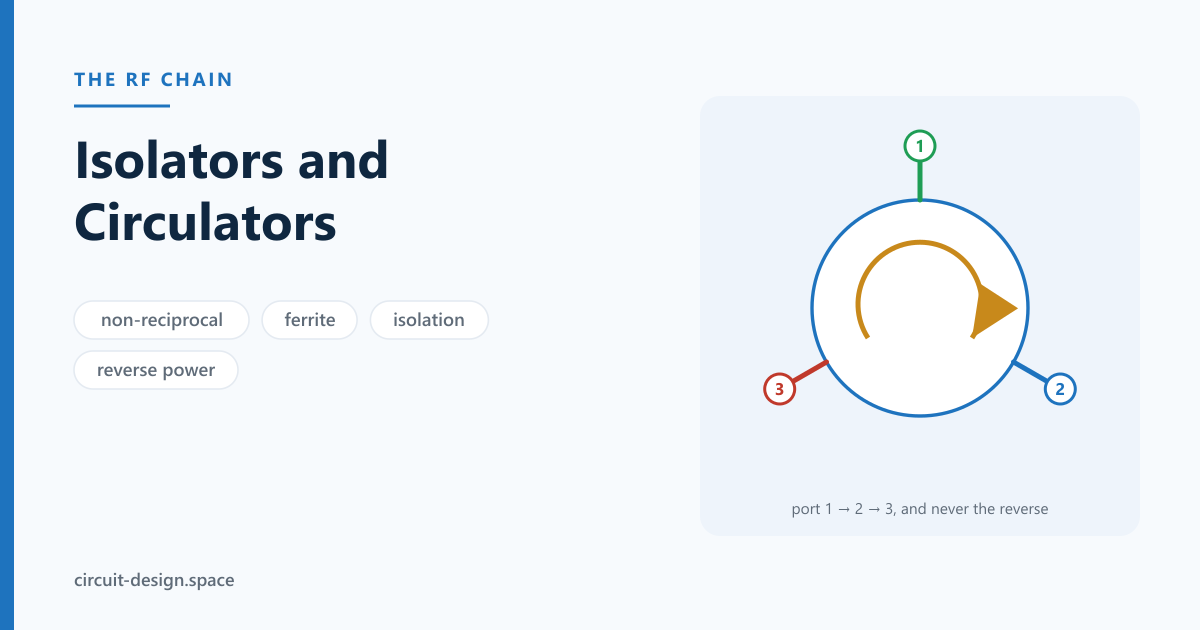
In a three-port junction, that difference is arranged so the fields add constructively toward one neighbouring port and destructively toward the other. The result is circulation: port 1 → port 2 → port 3 → port 1, and not the reverse.
An isolator is simply a circulator with its third port terminated in a matched load. Forward power passes; reverse power is routed into the termination and absorbed as heat rather than reaching the source.
The two numbers that set what a ferrite can do
The precession rate is the Larmor frequency, and for a ferrite it is set by the internal bias field through the gyromagnetic ratio MHz/Oe:
| Operating frequency | Required bias field |
|---|---|
| 1 GHz | ≈ 357 Oe (0.036 T) |
| 3 GHz | ≈ 1071 Oe (0.107 T) |
| 10 GHz | ≈ 3571 Oe (0.357 T) |
| 30 GHz | ≈ 10 700 Oe (1.07 T) |
Those fields are why the part contains a magnet, why its size does not shrink with frequency the way most passives do, and why a millimetre-wave isolator is a genuinely difficult object.
The second number is the ferrite’s saturation magnetisation, and it sets the lowest usable frequency. Below roughly the material enters the low-field loss region, where the RF field couples into unsaturated domain structure and is simply absorbed:
| Usable above roughly | |
|---|---|
| 0.3 kG | 0.8 GHz |
| 0.8 kG | 2.2 GHz |
| 1.0 kG | 2.8 GHz |
| 1.8 kG | 5.0 GHz |
| 3.0 kG | 8.4 GHz |
| 5.0 kG | 14 GHz |
This is the real reason there is no small, cheap isolator at VHF: a low-frequency device needs a low- garnet and a physically large junction, because the junction dimensions scale with wavelength in the ferrite. Below a few hundred megahertz the part becomes a brick, and designers reach for a balanced amplifier or a VSWR loop instead. Above about 2 GHz the economics reverse and a surface-mount isolator is a few dollars.
Devices run below resonance (bias field below the value in the first table, the usual choice, low loss and moderate bandwidth) or above resonance (higher field, used where bandwidth matters more). Which one a part uses is rarely on the datasheet and explains most of the differences you will see between two nominally similar devices.
2. The specification
| Parameter | Meaning | Typical |
|---|---|---|
| Insertion loss | forward direction | 0.2–0.5 dB |
| Isolation | reverse direction | 18–25 dB |
| Return loss | at each port | 18–23 dB |
| Bandwidth | where all of the above hold | 10–20%; octave designs exist and cost |
| Power handling | forward, and reverse into the termination | two separate numbers |
| Temperature range | over which the bias holds | the usual limiter |
| IMD / PIM | ferrites are nonlinear at high power | matters on duplexed systems |
Power handling has two ratings and people quote one. The forward rating is about the ferrite; the reverse rating is about how much the internal termination can dissipate. The reverse figure is the one that fails, and it is easy to compute: the termination absorbs .
| Forward power | Load VSWR 2:1 | VSWR 10:1 | Open or short |
|---|---|---|---|
| 1 W | 0.11 W | 0.67 W | 1.00 W |
| 10 W | 1.11 W | 6.69 W | 10.0 W |
| 50 W | 5.56 W | 33.5 W | 50.0 W |
| 100 W | 11.1 W | 66.9 W | 100 W |
An isolator protecting a 50 W PA against a disconnected antenna must dissipate the full 50 W in a resistor the size of a fingernail — and many parts rated “50 W forward” are rated at 5 or 10 W reverse, because the assumption is that the mismatch is transient. Whether that assumption holds is a system question: a broken feeder or an iced antenna is not transient, and the isolator becomes the thing that fails instead of the PA. If the fault case is indefinite, either specify the reverse rating at full forward power or add a thermal interlock, and remember that the heat now has to leave the isolator’s body — which means it needs a thermal path, not just a footprint.
3. What they are actually for
Protecting a PA from load VSWR. The main use. An antenna that is detuned, iced, blocked or disconnected presents a high VSWR at some phase that can destroy the output device. With 20 dB of isolation:
| Load VSWR | at the load | PA sees | PA sees VSWR |
|---|---|---|---|
| 2.0 | 0.333 | 0.033 | 1.069 |
| 3.0 | 0.500 | 0.050 | 1.105 |
| 10.0 | 0.818 | 0.082 | 1.178 |
A catastrophic 10:1 becomes a benign 1.18:1 at the device. That is the whole value proposition, and it is why 0.3–0.5 dB of forward loss is worth paying.
Duplexing a radar. A circulator lets one antenna transmit and receive: the transmitter feeds port 1, the antenna is port 2, the receiver is port 3. Transmit power goes to the antenna, returns go to the receiver, and the transmitter is isolated from the receiver by the circulation. The limit is that isolation is only ~20 dB, so a high-power radar still needs a transmit/receive switch or a limiter to protect the LNA.
Stabilising an oscillator or amplifier. A stage that sees a varying load can pull in frequency or become unstable. An isolator gives it a constant load regardless of what is downstream — a way to buy stability margin without redesigning the amplifier.
Preventing inter-stage interaction. Two cascaded stages that both have imperfect matches form a resonant cavity between them, producing gain ripple. An isolator between them breaks the loop.
4. The practical problems
They are magnetically fussy. The bias comes from a permanent magnet, and the device’s behaviour depends on the field being right. A steel bracket, another magnet, a transformer or a motor nearby will disturb it. Mechanical placement is an electrical decision, and this surprises people who treat the isolator as a component rather than a magnetic assembly.
They drift with temperature. The bias field and the ferrite’s magnetisation both vary, so insertion loss and isolation degrade at the extremes of the rated range. Temperature-compensated designs exist and cost more.
They are narrowband. 10–20% is typical. Octave-bandwidth designs exist but give up isolation and insertion loss to get there.
They are nonlinear at power. Ferrites generate intermodulation, which on a duplexed system lands in the receive band as PIM.
They are bulky and they are not cheap, which is the actual reason they get designed out.
5. The alternatives
| Approach | Isolation | Trade |
|---|---|---|
| Ferrite isolator | 18–25 dB | size, cost, magnets, narrowband |
| Active quasi-circulator | 20–30 dB | adds noise and nonlinearity; integrable |
| Balanced amplifier with quadrature hybrids | effectively good input/output match | doubles device count; classic and reliable |
| VSWR protection loop | none — it detects | needs a coupler and control; no forward loss |
| Spatio-temporal modulation | research/early product | non-magnetic non-reciprocity; linearity cost |
| Attenuator pad | 2× the pad value | brute force; throws away signal both ways |
The balanced amplifier deserves mention because it is often the right answer on a board: two identical amplifiers between 90° hybrids present a good match by cancellation, so reflections from the devices are absorbed in the hybrid’s terminations. You pay two devices instead of one and get a match that does not depend on a magnet.
A pad is the crude option and sometimes correct: 3 dB of attenuation gives 6 dB of return loss improvement for reflections, at the cost of 3 dB each way. On a receive path where noise figure is not critical, it is cheap and completely reliable.
6. Sourcing, which is unlike the rest of this chain
Worth saying plainly, because it surprises people used to buying everything from one distributor: ferrite isolators and circulators are largely not a mainstream distribution item. The specialist suppliers — DiTom Microwave, Pasternack, Fairview Microwave, RF-Lambda, UIY, Renaissance — sell them directly and by band, and that is where you will find the part you need. Some surface-mount parts do appear in general distribution, but the catalogue is thin compared with what the specialists carry.
The parts that are everywhere are the alternatives, and for a board-level design those are usually the better answer anyway:
| What you need | Distributor part | Notes |
|---|---|---|
| 90° hybrids for a balanced amplifier | Mini-Circuits QCN series, TTM/Anaren Xinger hybrids | two devices instead of one, and no magnet |
| Coupler for a VSWR-protection loop | Mini-Circuits SYDC-20-62HP+ | detection rather than absorption, zero forward loss |
| Power detector to close that loop | Analog Devices ADL5511, AD8318 | the loop’s real limit is usually here |
| Attenuator pad | Mini-Circuits / Vishay SMT pads | crude, reliable, and sometimes correct |
When specifying a real isolator, the four numbers to send a supplier are: frequency band, forward power, reverse power at worst-case mismatch, and temperature range — in that order. Bandwidth and isolation follow from them, and the supplier will tell you quickly if the combination does not exist.
7. The pitfalls
- Quoting only the forward power rating; the internal termination is what fails.
- Mounting near steel, a magnet, or a transformer.
- Assuming the datasheet’s isolation holds at the temperature extremes.
- Designing a duplexed system as if 20 dB of isolation were enough to protect a receiver.
- Forgetting PIM on a system that transmits and receives simultaneously.
- Treating the 0.3–0.5 dB of forward loss as negligible in a link budget where it is not.
- Putting one in a receive path in front of the LNA — that loss is noise figure, one for one.
- Specifying an isolator below the ferrite’s low-field-loss frequency and wondering where the insertion loss came from.
- Sizing the internal termination for a transient fault when the real fault is permanent.
- Forgetting that the absorbed reverse power is heat that has to leave the part.
Further reading
- David Pozar, Microwave Engineering. Chapter 9 covers the Polder permeability tensor, Faraday rotation and the junction circulator — the physics in §1, done properly.
- Robert Collin, Foundations for Microwave Engineering. A deeper field-theoretic treatment of gyromagnetic media.
- Benjamin Lax and Kenneth Button, Microwave Ferrites and Ferrimagnetics. The classic reference, if the subject becomes your problem rather than a component choice.
- Guillermo Gonzalez, Microwave Transistor Amplifiers: Analysis and Design. For the balanced-amplifier analysis that is the usual alternative to a ferrite.
The RF chain, block by block —Antenna · Filter · LNA · Mixer · LO · IF & ADC · PA · Isolator · Coupler · Overview
Glossary
— The ferrite’s saturation magnetisation, in gauss, and what sets the lowest usable frequency: below roughly the material enters low-field loss and simply absorbs. A 1 kG garnet is unusable below about 2.8 GHz, which is why there is no small, cheap isolator at VHF.
Balanced amplifier — Two identical amplifiers between 90° hybrids. Reflections from the two devices recombine into the hybrid’s termination, giving a good match by cancellation rather than by a magnet. Often the right answer on a board: two devices instead of one, and nothing to demagnetise.
Below-resonance / above-resonance — The two bias regimes a junction device can use. Below resonance is the usual choice, with lower loss and moderate bandwidth; above resonance trades loss for bandwidth. Rarely stated on a datasheet, and it explains most differences between two nominally similar parts.
Faraday rotation — Rotation of the polarisation plane as a wave travels through a magnetised ferrite, and the mechanism behind the original waveguide isolators. Largely displaced by the junction circulator, which is smaller and easier to make.
Gyromagnetic ratio () — About 2.8 MHz/Oe. It converts the bias field into the precession frequency, so a 10 GHz device needs roughly 3570 Oe — which is why the part contains a magnet, why it does not shrink with frequency the way other passives do, and why a millimetre-wave isolator is genuinely hard.
Junction circulator — Three ports on a magnetised ferrite disc, arranged so the fields add toward one neighbour and cancel toward the other. The standard modern construction, and the reason the device is a three-port rather than a two-port.
Larmor frequency — The precession rate of electron spins about the bias field. Everything non-reciprocal about a ferrite follows from the RF field interacting differently with that precession depending on its sense of circular polarisation.
Low-field loss — The absorption regime below , where the RF field couples into unsaturated domain structure. Specifying a part below it produces insertion loss nobody can account for from the datasheet’s headline numbers.
PIM — Passive intermodulation. Ferrites are nonlinear at power, so a duplexed system gets intermodulation products landing in its own receive band from a component that is, nominally, passive.
Polder tensor — The permeability of a magnetised ferrite is a tensor, not a scalar, with off-diagonal terms coupling the transverse field components. That tensor is the formal statement of why reciprocity breaks, and it is the whole of the physics.
Quadrature hybrid — A 90° coupler, and the component a balanced amplifier is built from. Widely stocked as a surface-mount part, unlike the isolators themselves.
Reverse power rating — How much the internal termination can dissipate, as distinct from the forward rating. The one that fails: an isolator protecting a 50 W PA from a disconnected antenna must absorb 50 W in a resistor the size of a fingernail, and many parts rated “50 W forward” are rated far lower in reverse.
Related
- The RF chain overview
- The power amplifier — what the isolator is protecting
- The directional coupler — the alternative, detection rather than absorption
- The antenna — the load that misbehaves
- S-parameters — where reciprocity is defined and deliberately broken
Have a transmit chain that does not survive a detuned antenna, or a duplexed system with an isolation problem? That’s what we do. Reach us at circuit-design.space.
circuit-design.space · +1-971-357-1400 · anovickis@circuit-design.space